

For many applications dependent upon interaction with varying, broadband light sources, such as solar cells, CMOS image sensors or thermal sensors, device performance can be critically dependent on the illumination condition – the intensity, angle and frequency of light incident upon the device. Designers rely on simulation tools to gain insight into the complex light-matter interactions that govern device performance and to optimize operating characteristics over a broad range of frequencies and illumination angles. Many photonic design tools are not well suited to simulating non-normal illumination conditions due to restrictions in the conventional simulation boundary conditions. These restrictions pose challenges for device designers in regards to both speed and accuracy of simulation. This document discusses some of these simulation challenges, and introduces Lumerical’s Broadband Fixed Angle Source Technique, BFAST, which is specifically formulated to remove the wavelength to incident angle relationship in simulations of periodic photonic devices.
Periodic systems with non-normal incident angles
The most efficient way to simulate devices with periodic features is to include only one unit cell in the simulation domain. Periodic boundary conditions with plane wave sources can be applied to the single unit cell to calculate the response of a system with an arbitrary number of identical unit cells. This methodology works well for plane waves propagating at normal incidence to the device surface. However, for plane waves incident on the surface at an angle, special treatment is required. A typical approach is to use Bloch boundary conditions. While effective at a single frequency, Bloch boundary conditions have a significant limitation when applied to plane waves containing more than one frequency, as the injection angle changes as a function of frequency. This effect is depicted in Figure 1.
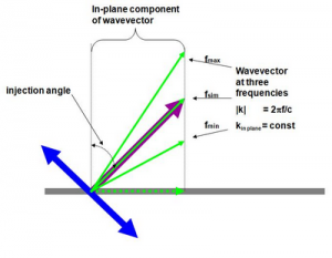
Figure 1: A plane wave source injects fields that have a constant in-plane wave vector at all frequencies. (a) shows a source with a nominal injection angle of 45 degrees (purple arrow). The in-plane wave vector (dotted green line) is chosen such that the actual injection angle at the center frequency of the simulation matches the nominal injection angle. Because the magnitude of the wave vector is proportional to frequency, the actual injection angle changes as a function of frequency, as can be seen (b).
As a result, while Bloch boundaries work well for narrow-band simulations, they cannot be applied to broadband simulations without introducing errors into the calculation. One way to overcome this limitation is by simple brute force; running a series of single wavelength simulations for each incident angle. The downside of the brute force approach is self-evident: it leads to a large number of simulations and a long time to compute the desired response.
Lumerical’s Broadband Fixed Angle Source Technique (BFAST)
An alternative solution to using Bloch boundary conditions is to reformulate the FDTD algorithm and remove the wavelength dependence of the injection angle. Lumerical has implemented an approach based on the split-field method [1, 2], and extended it to ensure it is compatible with multi-coefficient material (MCM) models, which accurately describe optical material properties over a wide wavelength range, and the conformal mesh. Analysis using BFAST, and comparisons to conventional Bloch boundary condition analysis are shown through select application examples in the following sections.
BFAST Analysis Application Examples
Dielectric Stack
To demonstrate the advantages of BFAST, consider the four-layer dielectric stack shown in Figure 2, the transmission of which can be calculated with the transfer matrix method.
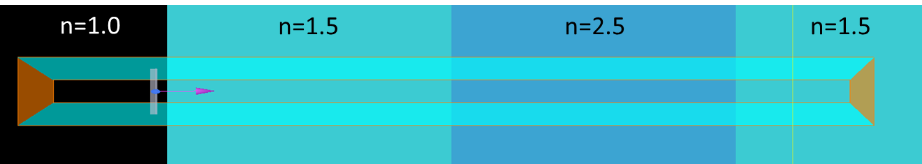
Figure 2: Four layer dialectric stack.
Figure 3 shows the transmission response as a function of wavelength and source angle calculated with FDTD using Bloch boundary conditions, BFAST, and the transfer matrix method, respectively. The result using Bloch boundaries and broadband illumination deviates significantly from theory due to the wavelength dependence of the injection angle. The BFAST simulation results correlate much more closely with the theoretical spectrum.
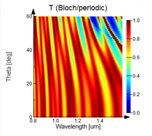
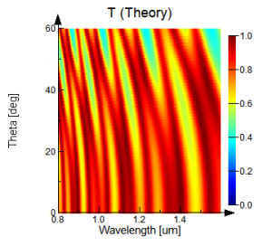
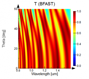
Figure 3: The broadband transmission for a four-layer dielectric stack calculated using Block boundaries, theory, and BFAST. The spectrum is shown as a function of wavelength and injection angle.
While BFAST removes the wavelength dependence of the injection angle, there are some performance considerations to note. There is a small computational overhead associated with BFAST compared to Bloch boundaries due to the changes in the FDTD algorithm implemented for BFAST. While typically negligible for small simulations, the overhead can increase the simulation time by up to a factor of 4 in certain cases, depending on the simulation size, type of materials and processor. The other consideration is that the simulation time for BFAST increases significantly as the injection angle increases. The simulation time increase due to reductions in the simulation time step necessary to maintain stability as the injection angle increases. The effect of this dependency is shown in Table 1.
| Angle (degrees) | 0 | 10 | 20 | 30 | 40 | 50 | 60 | 70 | 80 |
| Simulation time | 1.0x | 1.2x | 1.5x | 2.0x | 2.8x | 4.3x | 7.5x | 16.6x | 65.8x |
Table 1: The simulation time required for the simulating the dielectric stack using BFAST. The times shown are relative to the time required to run the same simulation at normal incidence.
Even with the added computational overhead associated with the BFAST implementation, for broadband simulations there is still a significant performance gain using BFAST rather than running single-wavelength simulations using Bloch boundaries. Furthermore, with BFAST, the wavelength resolution can be increased arbitrarily at almost no additional computational cost.
Lamellar Plasmonic Gratings
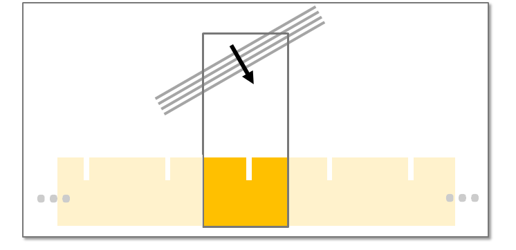
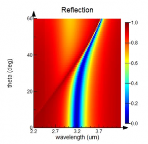
Figure 4: A plasmonic grating design based on ref. [3], featuring a gold surface with narrow and deep trenches. (b) The broadband reflection spectrum calculated using BFAST
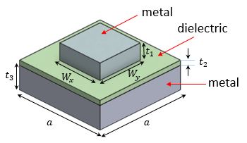
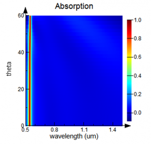
Figure 5: A typical metamaterial absorber design with a thin dielectric layer sandwiched between a top metallic sub-wavelength structure and a highly reflecting mirror [4]. (b) The absorption spectrum calculated using BFAST shows little dependence on the injection angle.
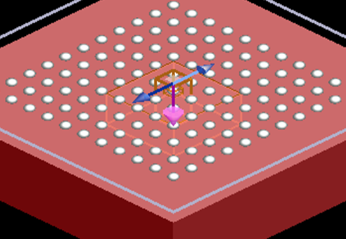
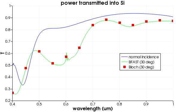
Figure 6: A silicon thin-film solar cell with nano-sized metal particles. (b) The power transmitted into the silicon layer for an injection angle of 0 and 30 degrees indicates that the performance of the solar cell is highly dependent on the illumination angle. One can see that important spectral features can be missed if there is not enough resolution in the spectrum.
For solar cells, broadband simulations are critical to optimize absorption across the solar spectrum at a number of different illumination angles in order to collect as much light as possible for all positions and orientations relative to the sun. To demonstrate the value of BFAST for such a design problem, Figure 6b shows the power transmitted into the silicon substrate of a plasmonic solar cell [6]. For an injection angle of 30 degrees, computing the entire spectral response using BFAST took 30 minutes. In comparison, the simulation using Bloch boundaries took 7 minutes for each of the 13 wavelengths computed to produce the result in Figure 6b with a significant loss of spectral information. To achieve the same resolution provided by BFAST, it would take more than one day of computation time using Bloch boundaries.
Summary
For photonic devices that are required to operate over varying illumination conditions, Lumerical’s BFAST can efficiently obtain accurate broadband results with a single simulation per angle, greatly reducing simulation time over alternative analysis methods that are restricted to narrowband frequencies. Highly accurate characterization and optimization of devices such as plasmonic solar cells, or metamaterial sensor arrays can be done minutes rather than hours or days. While BFAST offers significant performance gains for analysis involving broad spectra at moderate angles, for analysis of narrowband operation and steep incident angles, traditional Bloch boundaries should be considered due to the longer simulation time required for BFAST. For a truly powerful and accurate analysis toolkit, the combination of BFAST and Bloch boundaries provides designers with the best option for the illumination conditions under examination when optimizing devices with periodic features.
References
- A. Taflove, Computational Electronics: The Finite-Difference Time-Domain Method, Boston: Artech House (2005)
- B. Liang et al., “Wideband Analysis of Periodic Structures at Oblique Incidence by Material Independent FDTD Algorithm,” IEEE Trans. Antenna & Propagation, Vol. 62, No. 1, 354-360 (2014)
- N. Bonod et al., “Total Absorption of Light by Lamellar Metallic Grating,” Opt. Express 16, 15431-15438 (2008)
- J. Hao et al., “Nearly total absorption of light and heat generation by plasmonic metamaterials,” Phys. Rev. B 83, 165107 (2011)
- J. Talghader et al., “Spectral selectivity in infrared thermal detection,” Light: Science and Applications, Vol. 1, e24 (2012)
- S. Lim et al., “Photocurrent spectroscopy of optical absorption enhancement via scattering from surface plasmon polaritons in gold nanoparticles,” J. Appl. Phys. 101, 104309 (2007)